Configure Route-Based Site-to-Site VPN between Cisco Secure Management Center and AWS VPC
Introduction
The Secure Firewall Management Center (Management Center) features intuitive VPN wizards designed to streamline the configuration of site-to-site VPNs on managed Threat Defense devices.
These wizards also facilitate the setup of route-based site-to-site VPNs between Threat Defense devices and extranet devices. Extranet devices, which are not under the direct management of the management center, may comprise gateways located within public cloud infrastructures. Route-based VPNs use Virtual Tunnel Interfaces (VTIs)—routable logical interfaces that form the foundation of the VPN tunnel.
Is this Guide for You?
This guide is intended for network administrators who use the Management Center to establish a site-to-site VPN between a Threat Defense device located at the headquarters and an AWS Virtual Private Cloud (VPC).
Scenario
A medium-sized enterprise operates several branch offices, each with a set of instances hosted on AWS. This organization must establish a robust network infrastructure to facilitate secure and seamless communication across all locations. The solution involves configuring a site-to-site VPN that connects each branch's AWS VPC to the Threat Defense device at the organization's central headquarters. This connectivity is crucial because, by default, AWS VPC instances are isolated from external networks. The implementation of this VPN will enable the integration of the branches into the corporate network, ensuring centralized access and data security.
System Requirements
The following table shows the platforms for this feature.
|
Product |
Version |
Version Used in This Document |
|---|---|---|
|
Cisco Secure Firewall Threat Defense (formerly Firepower Threat Defense/FTD) |
6.7 and later |
7.4.1 |
|
Cisco Secure Firewall Management Center (formerly Firepower Management Center/FMC) |
6.7 and later |
7.4.1 |
|
AWS Account |
- |
- |
Benefits
The proposed solution offers significant benefits such as:
-
Streamlined Setup: VTI offers a simplified approach to VPN configuration, removing the complexity of traditional crypto maps and access lists.
-
Adaptive Routing: VTI accommodates dynamic routing protocols such as BGP, EIGRP, and OSPF, facilitating the automatic update of routes between VPN endpoints in response to changing network conditions.
-
ISP Resilience: VTI enables the creation of secondary backup tunnels, enhancing connectivity reliability.
-
Load balancing: VTI allows for the even distribution of VPN traffic through ECMP routing.
Prerequisites
-
Licenses: Management center Essentials (formerly Base) license must allow export-controlled functionality. Choose System > Licenses > Smart Licenses to verify this functionality in the Management Center.
-
Configure an internet-routable, public IP address for the Threat Defense device.
-
Assign appropriate logical names and IP addresses to the interfaces of the Threat Defense devices.
-
Own an AWS account.
Components of a Site-to-Site VPN between Management Center and AWS
A site-to-site VPN between the Management Center and AWS consists of the following components:
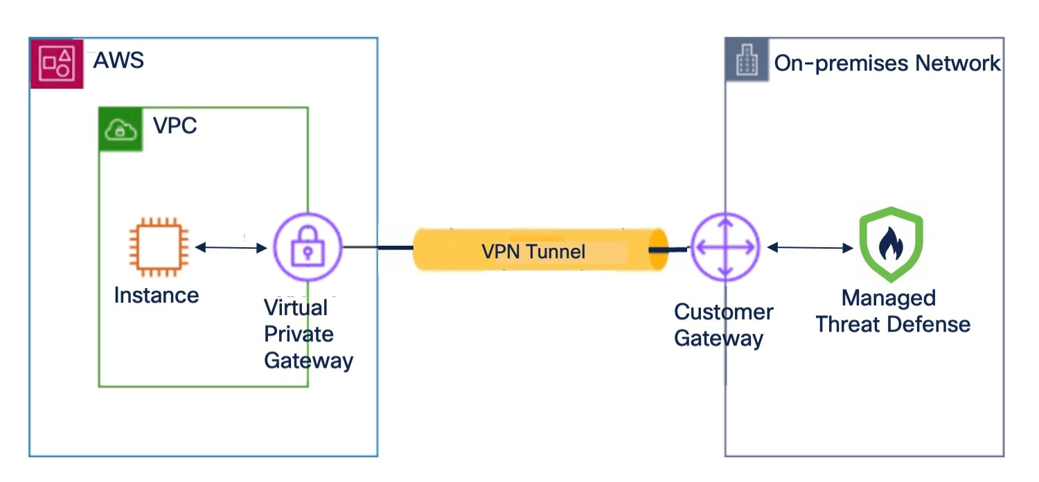
Virtual Private Gateway
A virtual private gateway is the VPN concentrator on the AWS side of the site-to-site VPN connection. You create a virtual private gateway and attach it to a virtual private cloud (VPC).
Customer Gateway
A customer gateway is a resource that you create in AWS that represents the customer gateway device in your on-premises network. When you create a customer gateway, you provide information about your device to AWS.
Customer Gateway Device (Managed Threat Defense)
A customer gateway device is the Threat Defense device in the on-premises network of your central headquarters. You configure the device to work with the AWS site-to-site VPN connection.
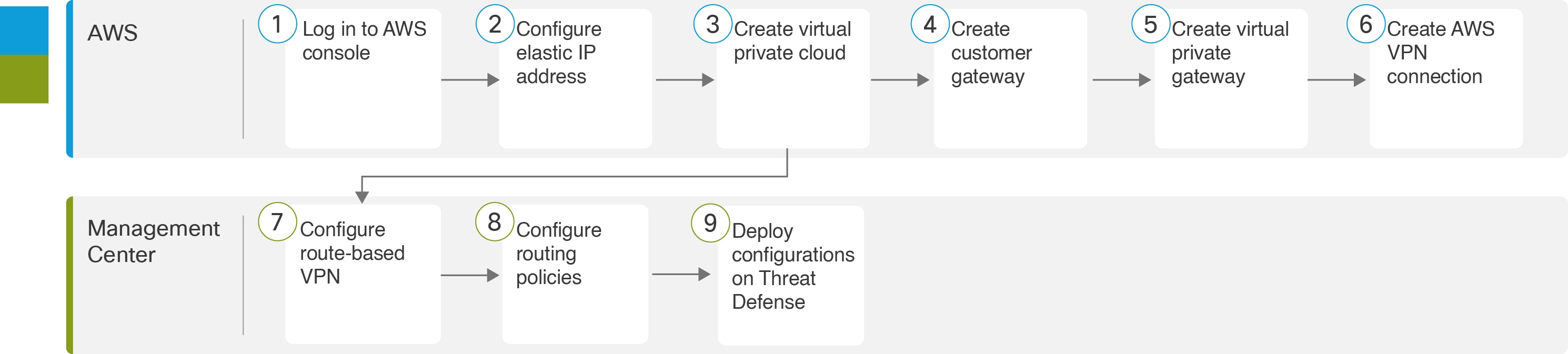
End-to-End Procedure for Configuring Route-Based VPN between Management Center and AWS VPC
The following flowchart illustrates the workflow for configuring a route-based VPN between Management Center and AWS VPC.
|
Step |
Description |
|---|---|
|
Log in to AWS console. |
|
|
Configure elastic IP address. See Configure an Elastic IP Address in AWS. |
|
|
Create virtual private cloud. See Create a Virtual Private Cloud in AWS. |
|
|
Create customer gateway. See Create a Customer Gateway in AWS. |
|
|
|
Create virtual private gateway. See Create a Virtual Private Gateway in AWS. |
|
|
Create AWS VPN connection. See Create a VPN Connection in AWS. |
|
|
Configure route-based VPN. See Configure Route-Based VPN in Management Center. |
|
|
Configure routing policies. See Configure Routing Policies in Management Center. |
|
|
Deploy configurations on Threat Defense device. |
Configure an Elastic IP Address in AWS
Elastic IP address is a static public IPv4 address that is allocated to your AWS account.
Procedure
|
Step 1 |
Choose Services > Networking & Content Delivery > VPC. |
|
Step 2 |
In the left pane, click Elastic IPs. |
|
Step 3 |
Click Allocate Elastic IP address. |
|
Step 4 |
Configure the following parameters in the Allocate Elastic IP address dialog box:
|
Create a Virtual Private Cloud in AWS
A VPC is a virtual network dedicated to your AWS account. It is logically isolated from other virtual networks in the AWS cloud. When you create a VPC, AWS configures the IP address, subnets, route tables, network gateways, and security settings.
Procedure
|
Step 1 |
Choose Services > Networking & Content Delivery > VPC. |
|
Step 2 |
In the left pane, click VPC dashboard. |
|
Step 3 |
Click Create VPC. |
|
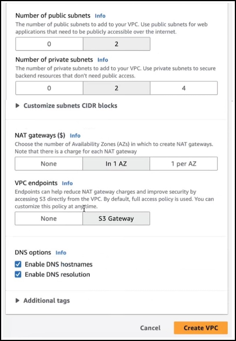
Step 4 |
Configure the following parameters in the Create VPC dialog box: 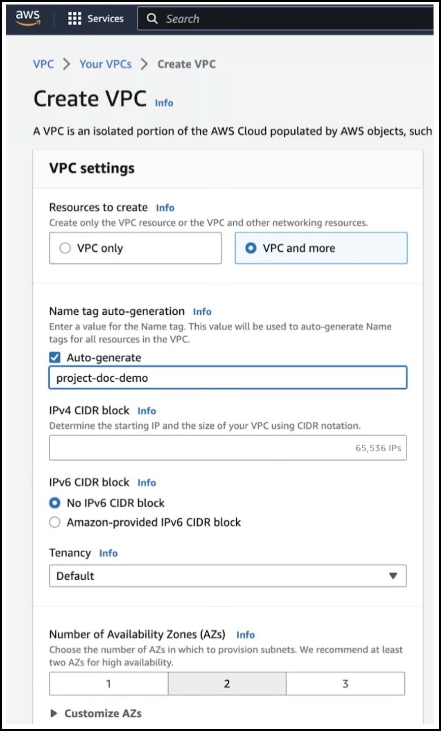
|
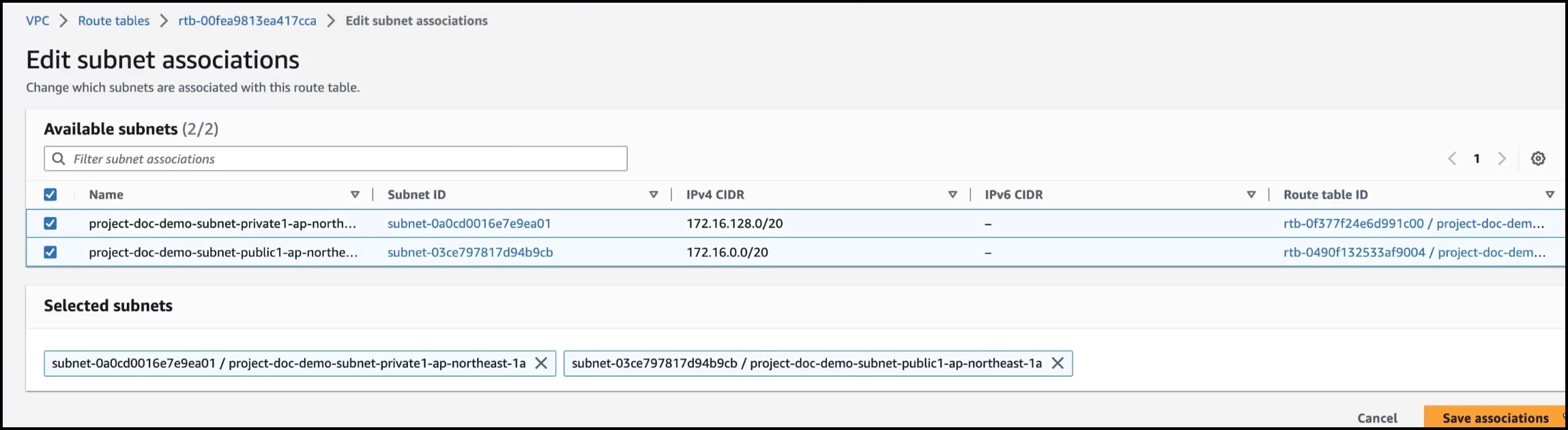
Associate a Subnet with a Route Table in AWS
You must associate each subnet in your VPC with the route table of your VPC.
Before you begin
Create a VPC in AWS.
Procedure
|
Step 1 |
In the left pane, click Route tables. |
|
Step 2 |
Select the route table assigned to your VPC. |
|
Step 3 |
Click the Subnet associations tab. |
|
Step 4 |
Click Edit subnet associations.
|
|
Step 5 |
Check the private and public subnet check boxes. |
|
Step 6 |
Click Save associations. |
Create a Customer Gateway in AWS
Create a customer gateway to provide information about your device to AWS.
Procedure
|
Step 1 |
In the left pane, expand Virtual Private network (VPN). |
|
Step 2 |
Click Customer gateways. |
|
Step 3 |
Click Create customer gateway. |
|
Step 4 |
Configure the following parameters in the Create customer gateway dialog box: 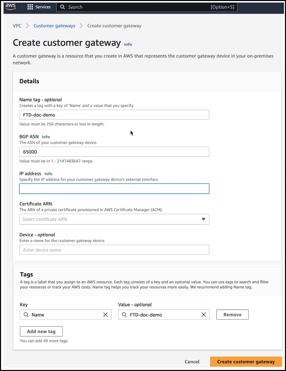
|
Create a Virtual Private Gateway in AWS
Procedure
|
Step 1 |
In the left pane, expand Virtual private network (VPN). |
|
Step 2 |
Click Create virtual private gateway. |
|
Step 3 |
Configure the following parameters in the Create virtual private gateway dialog box: 
|
Attach a Virtual Private Gateway to the Virtual Private Cloud
After you create a virtual private gateway, you must attach it to the VPC.
Procedure
|
Step 1 |
Select the virtual private gateway that you created. |
|
Step 2 |
Choose Attach to VPC from the Actions drop-down list. |
|
Step 3 |
In the Attach to VPC dialog box, choose the VPC from the Available VPCs drop-down list. |
|
Step 4 |
Click Attach to VPC. |
|
Step 5 |
Verify if the State of the virtual private gateway is Attached. 
|
Create a VPN Connection in AWS
Before you begin
Ensure that you have a VPC, customer gateway, and a virtual private gateway.
Procedure
|
Step 1 |
In the left pane, expand Virtual private network (VPN). |
||||||||||||
|
Step 2 |
Click Site-to-Site VPN connections. |
||||||||||||
|
Step 3 |
Click Create VPN connection. |
||||||||||||
|
Step 4 |
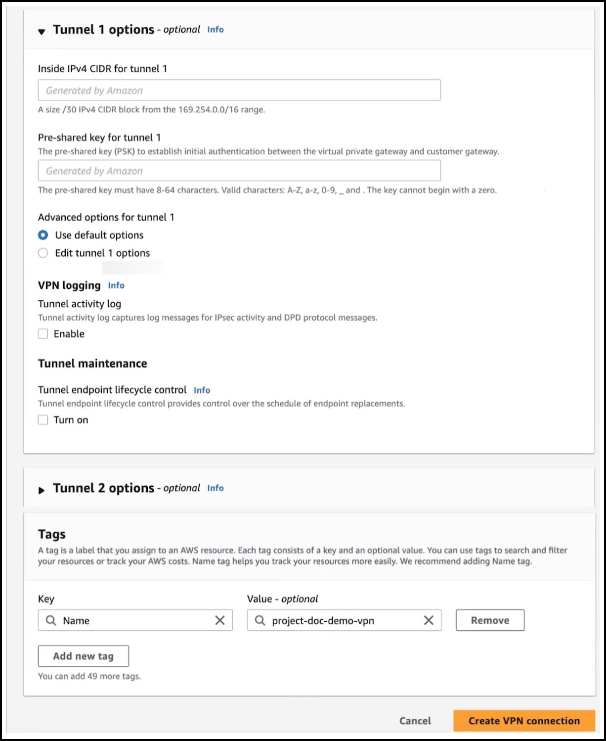
Configure the following VPN parameters in the Create VPN connection dialog box: 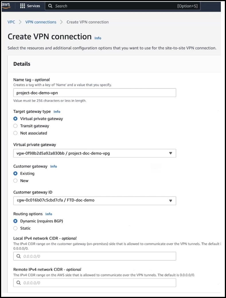
|
||||||||||||
|
Step 5 |
Click Create VPN connection. After the VPN connection is created, the State changes from Pending to Available.
|
Configure Route-Based VPN in Management Center
Before you begin
Ensure that you note the inside and outside IP addresses of the VPN tunnel in AWS.
Procedure
|
Step 1 |
Choose Devices > Site To Site. |
|
Step 2 |
Click + Site To Site VPN. |
|
Step 3 |
In the Topology Name field, enter a name for the VPN topology. |
|
Step 4 |
Click the Route Based (VTI) radio button. |
|
Step 5 |
Click the Point to Point tab. |
|
Step 6 |
Check the IKEv2 check box. |
|
Step 7 |
Click the Endpoints tab. |
|
Step 8 |
For Node A, configure the following parameters: |
|
Step 9 |
For Node B, configure the following parameters: 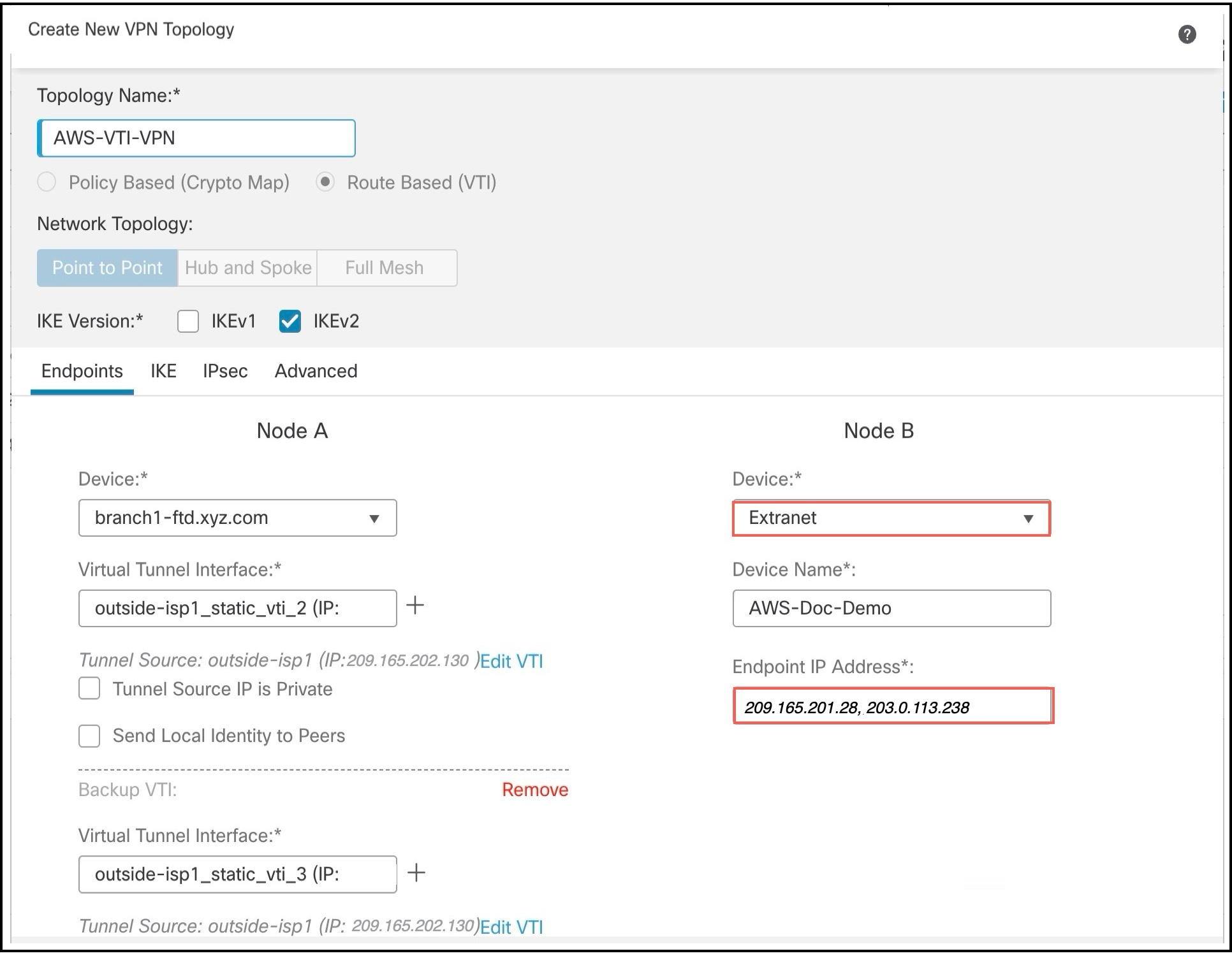 |
|
Step 10 |
Click the IKE tab to configure the following parameters: 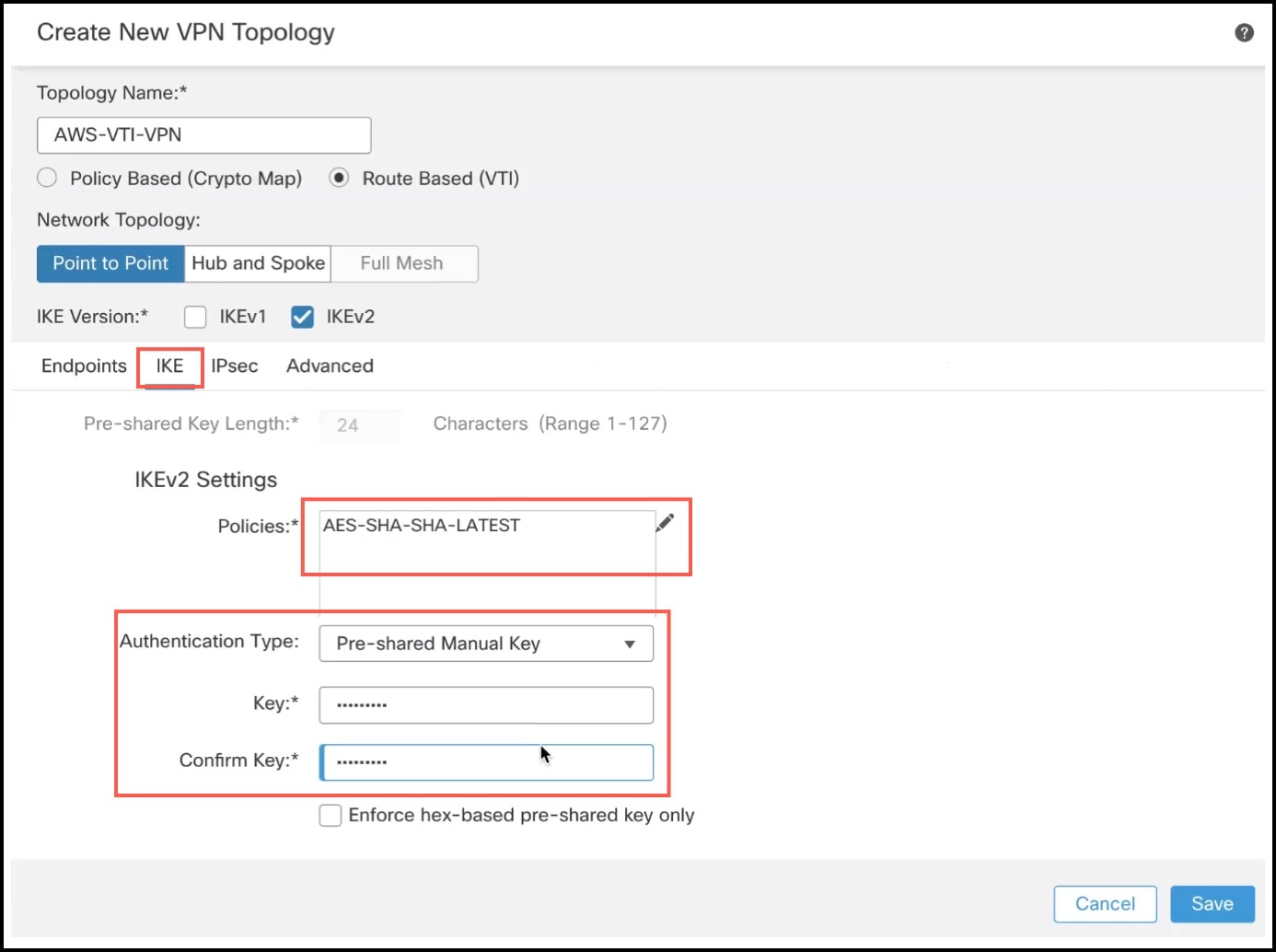 |
|
Step 11 |
For IPsec and Advanced configuration, use the default values. |
|
Step 12 |
Click Save. You can view the topology in the Site-to-Site VPN Summary page (Devices > Site To Site VPN). After you deploy the configurations to all the devices, you can see the status of all the tunnels in this page. |
Create a Static VTI for a Threat Defense Device in the Management Center
Before you begin
Configure the basic parameters for a route-based point-to-point VPN topology as described in Configure Route-Based VPN in Management Center, click the Endpoints tab, and choose a Threat Defense device from the Device drop-down list as Node A.
Procedure
|
In the Add Virtual Tunnel Interface dialog box, configure the following parameters: 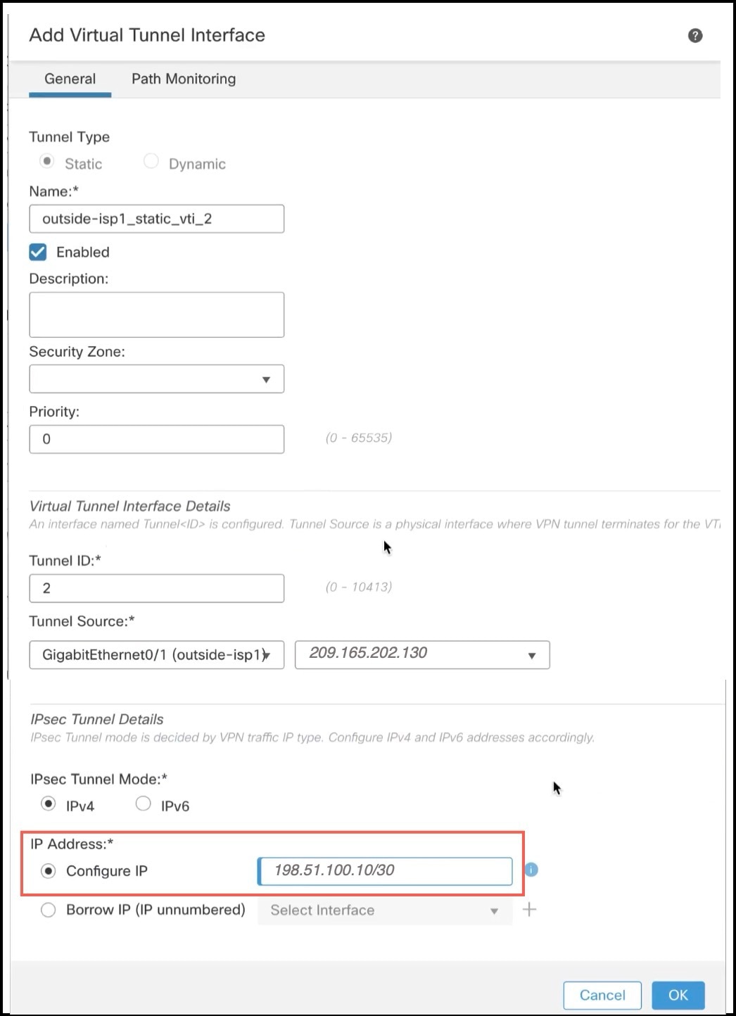 |
Configure Routing Policies in Management Center
Configure an Underlay Routing Policy in the Management Center
To enable traffic to and from the AWS, you must configure an underlay routing policy. You can configure a static route or any dynamic routing protocol. In our example, we use a static route.
Procedure
|
Step 1 |
Choose Devices > Device Management. |
|
Step 2 |
Click the edit icon adjacent to the interface that you want to edit. |
|
Step 3 |
Click the Routing tab. |
|
Step 4 |
In the left pane, click Static Route to configure a static route. |
|
Step 5 |
Click +Add Route. |
|
Step 6 |
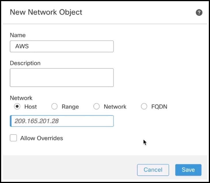
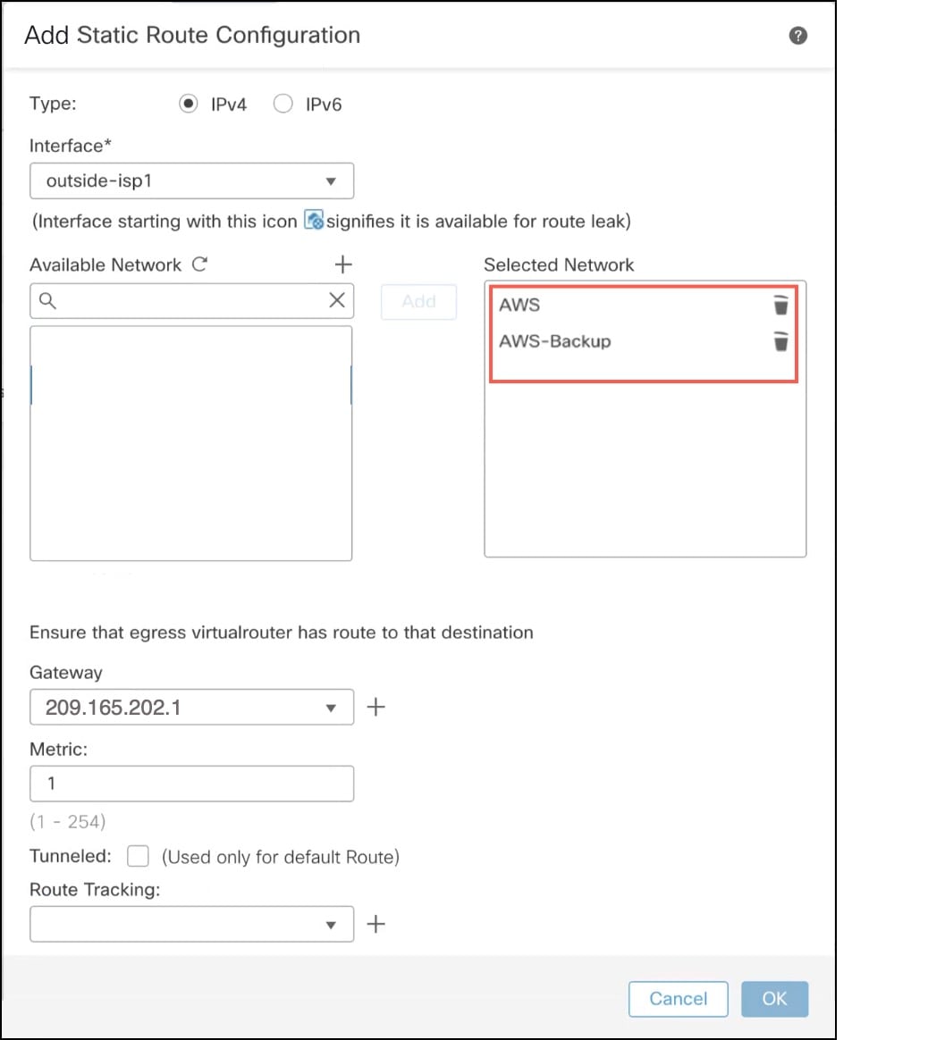
Configure the following parameters in the Add Static Route Configuration dialog box:
|
Configure an Overlay Routing Policy in the Management Center
You must configure an overlay routing policy for the VPN traffic. In our example, we configure a BGP routing policy.
Procedure
|
Step 1 |
Choose Devices > Device Management. |
|
Step 2 |
Click the edit icon adjacent to the interface that you want to edit. |
|
Step 3 |
Click the Routing tab. |
|
Step 4 |
In the left pane, click BGP under General Settings. |
|
Step 5 |
Check the Enable BGP check box. |
|
Step 6 |
In the AS Number field, enter the AS number of the Threat Defense device that you configured for the AWS customer gateway. In our example, it is 65000. |
|
Step 7 |
Click Save. |
|
Step 8 |
In the left pane, choose BGP > IPv4. |
|
Step 9 |
Check the Enable IPv4 check box. |
|
Step 10 |
Click the Neighbor tab and click +Add. |
|
Step 11 |
Configure the following parameters in the Add Neighbor dialog box: 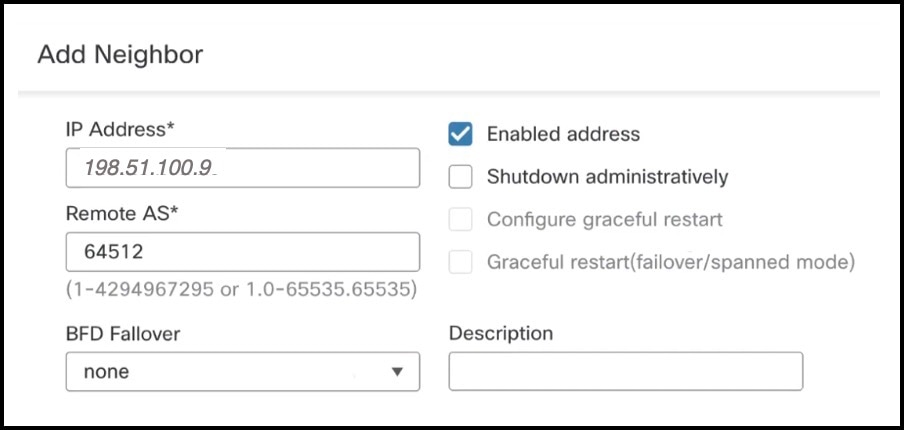 |
|
Step 12 |
Repeat Step 11a to Step 11c to add the backup AWS IP address (Tunnel2) as the neighbor. In our example, the IP address is 192.0.2.129 and the AWS AS number is 64512.  |
|
Step 13 |
Click Save. |
Verify the VTI Tunnel Statuses and Configurations
After deploying the configurations on the Threat Defense device, you can verify the VTI tunnel configuration and status on the device, the Management Center, and AWS.
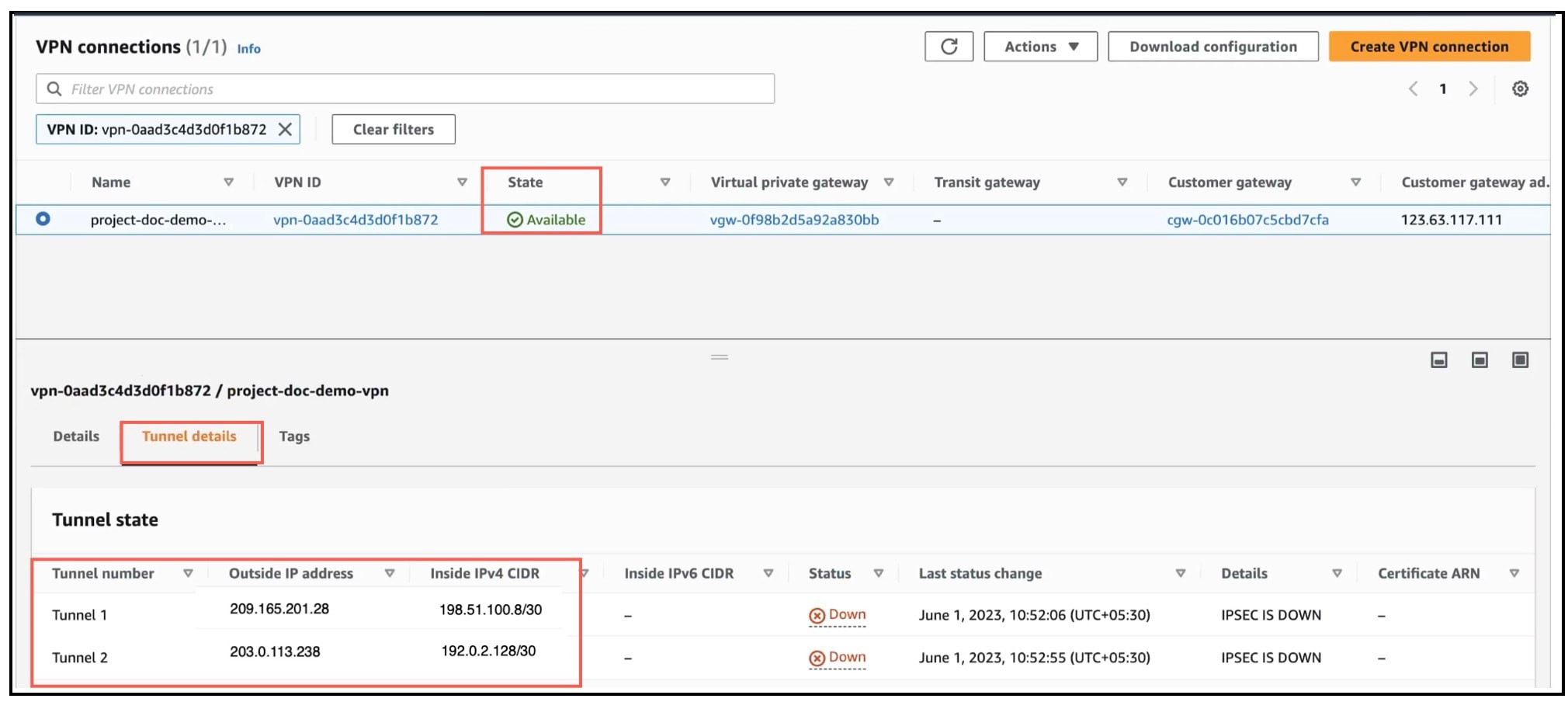
Verify Tunnel Statuses in AWS
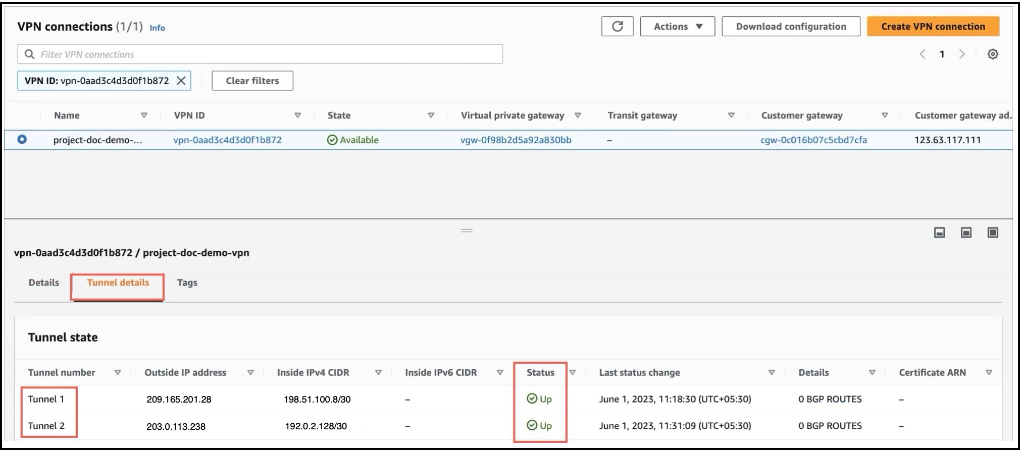
To verify the VPN tunnels in AWS:
-
Choose Virtual private network (VPN) > Site-to-Site VPN connections.
-
Click the radio button adjacent to the VPN.
-
Click the Tunnel details tab. The Status of the tunnels should be Up.
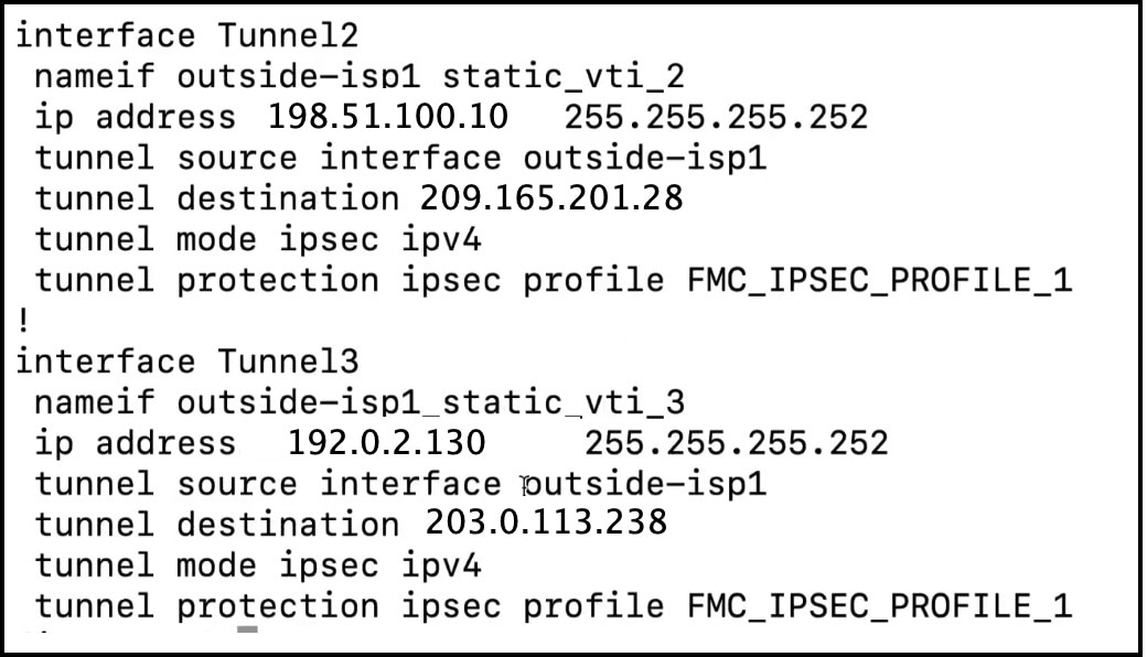
Verify Tunnel and Routing Configuration on the Threat Defense Device
-
To verify the interface configuration on the Threat Defense device, use the show running-config interface command.
-
To verify the BGP configuration of the Threat Defense device, use the show bgp command.
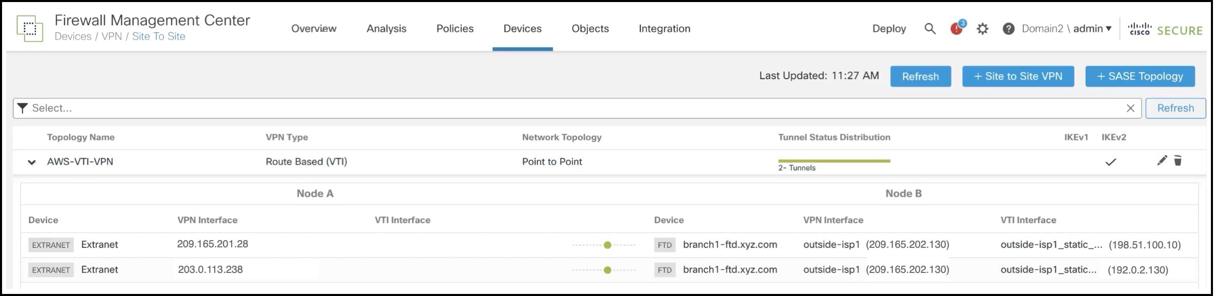
Verify Tunnel Status in Site-to-Site VPN Summary Page
To verify the status of the VPN tunnels, choose Device > VPN > Site To Site.
Verify Tunnel Status in Site-to-Site VPN Dashboard
To view details of the VPN tunnel, choose Overview > Dashboards > Site to Site VPN.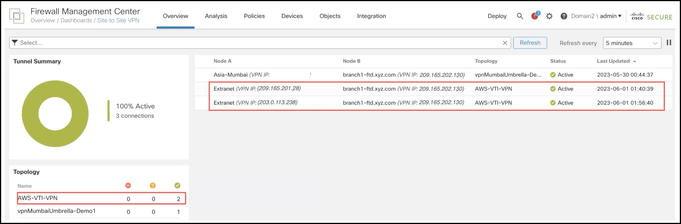
 Feedback